SPECIFICATIONS & Operations
2012 Ranger 29, built in Monroe, Washington by Ranger Tugs and delivered in November 2011
The following information is a synthesis from a variety of sources.
YANMAR 6BY260 ENGINE: This 6 cylinder, 3.0 liter engine has an aluminum block and was made by BMW, with a turbo made by Cummins and converted to marine use by Yanmar.
Alternator: Output-150 amps
Coolant thermostat starts to open at 190 degrees and is fully open at 205 degrees, BMW brand coolant/Anti-Freeze, 50/50 mix with distilled water creates a boiling point of 265 degrees, change every 500 hours or two years whichever comes first. Normal operating temperature is 193 degrees at low speed and 205 degrees at high speed. A little variation given the temperature of the water.
Oil: 10-30W, synthetic, 11.5 quarts, change every 250 hours or annually, whichever comes first, pressure is 14 psi at idle and 87 at wide open throttle
Starting Battery: 668 cold cranking amps recommended
RPM's, Speed (MPH), Fuel Use (MPG) and Operations:
Engine Operations:
Electrical System:
Water System:
- Length overall for slip: 33 feet
- Beam: 10 feet
- Height: Antenna Up-16', Tower Up-13', Tower Down-10'
- Draft: 2'6"
The following information is a synthesis from a variety of sources.
YANMAR 6BY260 ENGINE: This 6 cylinder, 3.0 liter engine has an aluminum block and was made by BMW, with a turbo made by Cummins and converted to marine use by Yanmar.
Alternator: Output-150 amps
Coolant thermostat starts to open at 190 degrees and is fully open at 205 degrees, BMW brand coolant/Anti-Freeze, 50/50 mix with distilled water creates a boiling point of 265 degrees, change every 500 hours or two years whichever comes first. Normal operating temperature is 193 degrees at low speed and 205 degrees at high speed. A little variation given the temperature of the water.
Oil: 10-30W, synthetic, 11.5 quarts, change every 250 hours or annually, whichever comes first, pressure is 14 psi at idle and 87 at wide open throttle
Starting Battery: 668 cold cranking amps recommended
RPM's, Speed (MPH), Fuel Use (MPG) and Operations:
- 650 is idle
- 650 to 1200 is warmup of coolant. Match the digits of the RPM to the coolant temperature, i.e. 1,000 RPM to 100 degrees, 1,200 RPM to 120 degrees, 1,400 RPM to 140 degrees, 1,600 RPM to 160 degrees, 1800 RPM to 180 degrees
- 1800 to 1900 is slow cruising speed: 7-9 MPH, 3.5 to 4.0 MPG, 1.8-2.2 GPH, engine load 50-60%
- 3150 to 3430 is fast cruising speed, 13-18 MPH, 1.5 to 2 MPG, engine load 70-80% with turbo at about 20 psi; (90% of the engine's use should be this or less)
- 4000 maximum output
- 4600 high speed idle
Engine Operations:
- Slight blue smoke is normal when cool
- Until oil is warm, sound of valves clicking is normal when cool, these are self-adjusting
- Alternator output is 14.2 volts on all battery banks
- Stay under 1800 RPM's until temperature reaches 180 degrees
- Gradual increase and decrease of RPM's is preferred
- Run higher RPM's during the first half of the cruise, for at least 20 minutes to exercise the turbo
- Run at less than 1800 for at least 20 minutes at the end of the cruise to cool down.
- Shut down when coolant temperature is less than 190 degrees
Electrical System:
- 30 AMP AC Shorepower, the breaker is located in the upper, upper, upper inside right corner of the transom storage locker, above the wash-down pump switch. This breaker is frequently tripped when the inverter switch is turned on before the main AC power switch
- Inverter/Charger: a flashing yellow light means it is charging the batteries, not a cause for alarm, the inverter has three stages: fast charge, bulk charge and maintenance charge. It is designed to be in a charging mode all the time. We do NOT use the auto feature on the control panel as we want to know and decide when the device is operating as an inverter and drawing down the batteries.
Water System:
- 70 gallon capacity
- There is a very close association with the capacity of the water system and the 40 gallon holding tank. When one needs attention, the other does too.
- Gauge functions when the water system pump is turned on. The water level is measured by a float on a rod that angles down and across the tank. It may sometimes stick
- Gauge shows full for 3/4 of its capacity and then shows the remaining 1/4 when being emptied. While filing, the gauge is fairly accurate. In the red zone, the tank is empty.
- Purifying water: 3 Tablespoons of beach (with no fragrances) in 70 gallons. We use the Brita filter/pitcher that fits nicely in the refrigerator for drinking water
- Andiamo has two fresh water pumps; one for the faucets and head, one for the wash-down in the cockpit
- Hot water; heated by the engine coolant or AC shorepower, the five gallon heater takes about 45 minutes to make hot water
- 40 gallon capacity. When the head's indicator light moves from green to yellow (or amber) the tank is more than half full. Serves a good warning to pump out, but it is not urgent. When the indicator flashes red, the system will flush but not add water. Basically the tank is full.
PROPANE SYSTEM
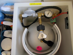
The propane system can be very safe and reliable if you pay attention to it. Propane can be very dangerious because it is heavier than air and if spilled and not properly vented can end up in the bilge and be an explosive. The fiberglass tank that came with the tug was recalled and replaced with an aluminum one that holds 2.83 gallons. When empty it weighs about 10 pounds and about 20 pounds when it is full. This amount of propane lasted 10 weeks of daily use. The tank pressure was 90 to 150 psi. The tank just fits in the box provided. Remove the sink, after disconnecting the drain hose (a threaded connection) and remove the propane box lid. The new tank comes out the left cabinet door, not through the sink opening. See the photo for the proper orientation of the tank to get the valve and the box lid to fit.
The propane system can be very safe and reliable if you pay attention to it. Propane can be very dangerious because it is heavier than air and if spilled and not properly vented can end up in the bilge and be an explosive. The fiberglass tank that came with the tug was recalled and replaced with an aluminum one that holds 2.83 gallons. When empty it weighs about 10 pounds and about 20 pounds when it is full. This amount of propane lasted 10 weeks of daily use. The tank pressure was 90 to 150 psi. The tank just fits in the box provided. Remove the sink, after disconnecting the drain hose (a threaded connection) and remove the propane box lid. The new tank comes out the left cabinet door, not through the sink opening. See the photo for the proper orientation of the tank to get the valve and the box lid to fit.
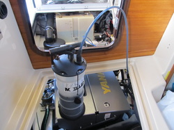
CHANGING THE ENGINE OIL AND FILTER ELEMENT,
Every 250 hours or annually whichever comes first
Oil: Mobil 1, full synthetic, 10-30W, capacity is 11.5 quarts, takes 10 quarts at change, buy 12 quarts. See manual for other oil options.
Materials: oil filter element with o-rings (compatible: Mahle Brand, Model OX177/3D plus Yanmar O-rings #165000-69580 & 69570), roll of blue shop towels, small box, plastic bags, recycle oil container that holds 12 quarts, tape, channel-lock wrench, o-ring removal tool
Steps:
1. Run engine at idle for 5 minutes, then put in forward or reverse after adding additional lines and idle in gear for 15-20 minutes to warm up oil.
2. Open both engine hoods, putting inside hood in the mid-berth cabin
3. Remove dipstick and oil filler cap, clean and put them on the hood so they are not disturbed.
4. Put towels around and underneath the element canister.
5. Assemble oil vacuum with two lines, get a good joint, and fully insert the tube to the bottom of the dip stick tube and start sucking oil out. After vacuum is full, pour the oil into the used oil container. Pours cleanly with minimal drips.
6. From the cockpit, use the channel locks to loosen the cap of the filter canister and turn two full rotations to allow air in and oil to drop into the pan. The canister will fully empty of oil.
7. Suck out the remaining oil. It will take about 2 ¼ fills of the vacuum container.
8. Remove the vacuum tubes, disassemble, clean, and let each drain in a plastic bag that has an absorbent pad and several towels.
9. Line the small box with a plastic bag and put it on the engine cover near the canister. Cover the engine cover with towels
10. Unscrew the canister. This is one assembly that comes out as a unit. With the oil drained out, there is minimal dripping. Lift the assembly out and put it in the cardboard box.
11. Using towels to grip the element and the cap, pull off the used element from the assembly. It is not screwed on, held in place by tension and slides off. May take another set of hands.
12. Use the o-ring removal tool to removal the largest o-ring on the cap, lube the new o-ring and roll into place, then use the o-ring tool to ensure no twists.
13. Install the new element by sliding it on the assembly and pushing it fully into the cap until the element seats.
14. Install the canister assembly, tighten the cap to hand and give it a snug with the channel locks.
15. With towels around oil filler and at the base of the new oil container, use a funnel, and pour in 1-¾ containers (about 8 quarts of oil). Check level with dipstick, roll the stick on a towel to better see the fluid level. Add until oil is between the marks.
16. Install dipstick and oil cap.
17. Run engine, be ready for momentary oil pressure alarm, checking for leaks and run for at least two minutes at idle.
18. Wait 10 minutes, recheck oil level and add if necessary.
19. Thoroughly wipe everything clean and especially the bilge.
20. Tape towels to the ends of the vacuum tubes, after they are finished draining, and store with vacuum & oil recycle container.
CHANGING THE TWO FUEL FILTERS
Every 250 hours or annually whichever comes first
Materials & Tools: Yanmar fuel fine filter #120651-55020 with new gasket or Parker/Racor R90-DS-RAC-01 this mounts on the engine, Yanmar water separating filter #120650-55010 with two gaskets, roll of blue shop towels, container to receive two cups of clean diesel fuel, small (1/2 c) container to receive dirty diesel fuel, funnel, 4 absorbent pads, plastic bags, slip-adjusting filter wrench
Steps:
The Fuel Fine Filter is located on the engine
1. Turn off the fuel by using the blue-handle shut off valve
2. Paper the surfaces below the filter with blue towels, as the filter is full of fuel.
3. Open the wrapper of the new filter, put the gaskets aside, have it nearby on blue towels with a funnel installed
4. This was only hand-tightened and should come off with the slip-adjusting filter wrench. Turn filter to the left, which is counter clockwise, if looking at it from the bottom to the top.
5. When the filter comes off, pour the diesel into the new filter using the funnel.
6. Make certain the old rubber gasket came off, as it may stick to the engine side and cannot be seen.
7. Lube the new gasket and install it on the new filter.
8. Turning the filter to the right, install and hand-tighten
9. Bleed air from the fuel system by opening fuel valve and turning ignition key to the first stop. The fuel pump will push fuel through the system and fill the filters. When the sound at the fuel system stops, stop, wait 5 seconds, and repeat five times. Start the engine and run it for 2-3 minutes checking for leaks.
Fuel Filter/Water Separator is mounted on the left bulkhead near the fuel shut-off valve
1. Turn off the fuel at the blue-handle shut-off valve. The following instructions are different from the manual:
2. Contrary to the manual, the drain plug does not remove.
3. Disconnect the water sensor at the wiring connection about 8 inches from the sensor. The tab lifts away so you can gently pull the connection apart.
4. Paper the area below the filter and into the bilge with absorbent pads and towels.
5. The filter assembly has two parts, the filter canister and a bowl. Leave this assembly intact. Unscrew the filter/bowl assembly by turning it to the left. It was hand-tightened but may need the slip-adjusting wrench.
6. The filter will be full of fuel. Pour the fuel into a clean 2-3 cup container.
7. Unscrew the bowl by rotating it counterclockwise with the water senor still attached. Dirty diesel may be there. Pour into a different small container and clean out the bowl. Remove the old gasket.
8. Lube the new gasket with fuel, install on the bowl and screw the bowl onto the new filter and hand-tighten.
9. Lube and install the new gasket to the top of the new filter.
10. Turning the filter to the right, install and hand-tighten.
11. Re-connect sensor to the wiring harness.
12. Bleed air from the fuel system by opening fuel valve and turning ignition key to the first stop. The fuel pump will push fuel through the system and fill the filter. When the sound at the fuel system stops, stop, wait 5 seconds, and repeat five times. Start the engine and run it for 2-3 minutes checking for leaks.
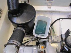
COOLANT CHANGING PROCEDURE
Every 500 hours or two years, whichever comes first.
Materials & Tools:
A. 2 gallons of BMW coolant concentrate available at the BMW dealer. I spent hours reading websites and service bulletins by authorized repair shops to find a coolant that was more widely available. The approved coolants listed in the operating manual are not available in the national stores. Take what you read on the Internet with an ounce of skepticism as the consequences of using the wrong coolant can void the warranty and do very significant damage to the engine. In the end, I paid more but got the coolant that was put in by the factory and I have piece-of-mind, which is worth the price.
B. 2 gallons of distilled water. Do not use city water because of the unknown chemical content
C. 3 feet of 3/8” hose, inside diameter
D. Funnel with at least 8” of flexible tubing because the filler port on the engine is right under the cabin door
E. Factory-provided, white starboard, coolant cap removal assistant
F. Rectangular, 2 gallon bucket
G. Transport container for old coolant to properly dispose of it
H. Roll of shop towels
Steps:
1. Engine is cold for at least 12 hours. Work from the engine compartment side for the following steps.
2. Use the coolant cap removal assistant to take off the cap and use a towel to clean it.
3. Paper under the area under the coolant drain cock with shop towels
4. Put the rectangular bucket in the lowest part of the bilge. Getting it lower than the drain cock is the goal.
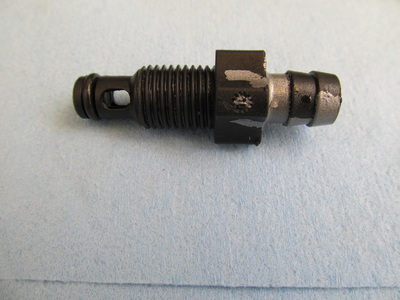
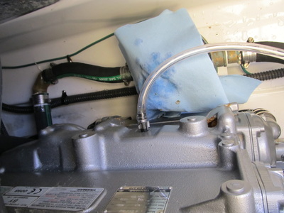
5. The coolant drain cock is on the starboard side of the engine, easily accessible and has hose barb on the end. It is plastic and is threaded into the block and hand-tightened. Use a crescent wrench to gently loosen it.
6. Attached the 3/8” hose to the drain cock as it slides on to the barb. Put the other end in the bucket and use tape or string to support the middle of the hose.
7. Hold the hose still, and rotate the drain cock open until ½” of threads are showing. See the photo of what the drain cock looks like. The drain cock is threaded into a passage, not into a pan or space.
8. The coolant will come out a very slow trickle. About two gallons, 8 quarts of the 12, will come out the drain and will take over an hour to do so. Be patient. Transfer the old coolant in the bucket, to the transport container as necessary.
9. Remove the drain cock, wipe it clean, and re-install it. Hand-tighten.
10. Using the funnel with the flexible tube, pour a gallon of new coolant into the filler port. Then pour in a gallon of distilled water. This may initially fill the block.
11. Leave the cap off and start the engine and let it come up to operating temperature, this will take at least 30 minutes. Watch for the bubbles in the block to rise up and run until no more air bubbles come up.
12. From the cabin side, open the expansion tank, remove the cap and inlet hose and wipe it dry. Lift out the tank from its brackets by lifting straight up. Empty the old coolant and rinse clean. Re-install the expansion tank and fill with 2 inches of coolant-water, 50/50 mix.
13. Thoroughly wipe up all the fluids in the bilge and engine compartment.
14. Run the engine to full operating temperature while monitoring the temperature. Any temperature over 210 degrees, return to dock and shut down as coolant is needed. Regardless, after a thorough cooling down period, over night is preferred, check the coolant level by removing the cap (not the expansion tank) and add 50/50 mix to completely fill it. A 50/50 mix will create a boiling point of 265 degrees. Continue to check the level before each use.

RUNNING IN FOG
Of course, do not run in fog unless you feel safe about it. Otherwise, stay in port or at anchor and wait it out. We do not plan to run in fog but it has enveloped us. This is what we do:
Run Slow. No faster than 8 MPH.
Turn on the running lights & sound the horn for 4 to 6 seconds at two minute or less intervals. You want to be seen and heard by those who you cannot see.
Know your radar and use it. We run with radar most of the time and have learned what its capabilities are and have confidence in what it does. Typically, the radar view is equal to what distance can be traveled in five minutes. At 8 MPH, that is about 3/4 of a mile.
One person maintains a sweeping side-to-side forward lookout while the helmsman runs by the instruments. Open the windows and keep a quiet pilothouse to listen for the sounds of other boats. Steering in the fog is really difficult. Use a chartplotter and autopilot to help. The radar will pick up targets that may vanish quickly, especially small bass boats, and the helmsman have have a very short period of time to throttle back and to avoid a collision.
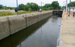
LOCKING THROUGH
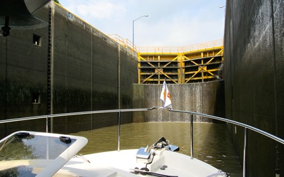
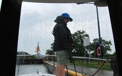
Our approach to these locks was easy and successful. Each kind of locks requires a new system and approach based on how the lock is equipped with cables or ropes or floating bollards. The goal is to be flexible.The lockmaster is called on the radio when the lock is seen and it is entered when the gate is opened. The large ball fenders were hung high on the gunwale for the lock wall and the normal docking fenders are also hung but lower to catch the top of the lock wall as sometimes these edges are angled away from the tug.
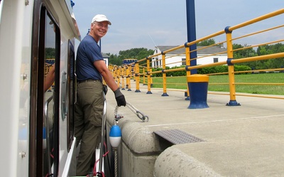
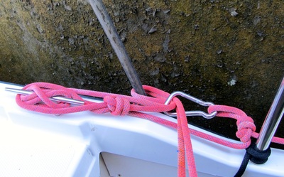
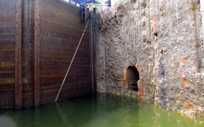
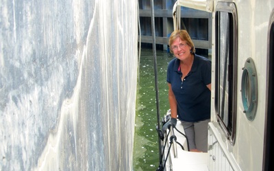
On the Erie Canal, Laurie would be on the bow with a life jacket. Andiamo was idled into the lock and aimed toward the ropes on the starboard side and close to the forward gate. A suitable pair of hanging ropes was identified, as some were too far apart for Andiamo’s length. Forward idle goes to neutral and then reverse for half a boat length so Laurie can get the first rope. Staying in reverse at idle speed until the second rope is at the stern, neural gear, and I walk back and grab the rope. The lock lines are always put under a cleat’s horn to take the strain, never cleated, and just held on with gloved hands. As the tug is lifted, the slack is pulled through the cleat. The objective is to keep control of the tug, let the fenders protect the fiberglass, and having a space between the fenders and the lock wall is preferred. When the lock gates are fully opened, the tug is idled out the lock.
On the Trent-Severn Waterway, the spacing of the stretched, vertical cables was different. Laure would stay in the cockpit, I got a cable through the open sliding door and stopped the tug, then Laurie could easily reach a cable. The Trent-Severn staff required that lines were attached to two cables for more stability.
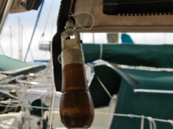
DOING MINOR CANVAS REPAIRS
By paying attention to the canvas and especially the stress points where a repair would likely happen, you can head off bigger problems. Here, the thread that holds the end of the zipper has broken and the zipper will start to separate from the canvas. The repair is done with a sewing awl that is loaded with wax linen thread. The awl is inserted to the existing holes and about 10 stitches were made that took about 20 minutes to do. Stitching will deteriorate and the fix to have all the seams re-sewn by a canvas shop - takes a few hours and is affordable.
By paying attention to the canvas and especially the stress points where a repair would likely happen, you can head off bigger problems. Here, the thread that holds the end of the zipper has broken and the zipper will start to separate from the canvas. The repair is done with a sewing awl that is loaded with wax linen thread. The awl is inserted to the existing holes and about 10 stitches were made that took about 20 minutes to do. Stitching will deteriorate and the fix to have all the seams re-sewn by a canvas shop - takes a few hours and is affordable.
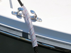
CHAFE PROTECTION
Great lines can be destroyed in short order by rubbing and chafe. This 12" long plastic hose with a diameter that matched the line, was slid over the lines were contact is made. To make the install easier, soak 24" of the end in soapy water, pour soap inside the hose and when stuck, warm up the hose with a hair dryer and push it through by twisting the hose into the line. While you at it, wash the lines in a bucket of fresh water with soap and they will be soft and flexible again with the salt and grime gone.
Great lines can be destroyed in short order by rubbing and chafe. This 12" long plastic hose with a diameter that matched the line, was slid over the lines were contact is made. To make the install easier, soak 24" of the end in soapy water, pour soap inside the hose and when stuck, warm up the hose with a hair dryer and push it through by twisting the hose into the line. While you at it, wash the lines in a bucket of fresh water with soap and they will be soft and flexible again with the salt and grime gone.
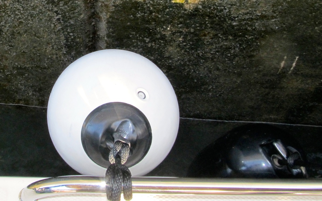
FENDERS-THE WORKER BEES
If you take care of the fenders, they will take care of your tug. This photo shows the two kinds of fenders that Andiamo carries. The black ones are about 9" in diameter and 26" long, (we use Polyforms, model G-5) and the tug has three for each side, tied to the rails and ready for deployment.
The white fall fender is roughly 12" in diameter is used for lock walls, harbor walls and sometimes fixed docks where the pilings are on the outside of the dock. These are stored on the roof, looped through the solar panel brackets and tied to the sport rack for easy use or they are deflated and buried in storage.
The fenders are cleaned with water/vinegar solution regularly because the grime rubbed into their finish will be an abrasive on the gelcoat. When they are kept clean, fender covers are not necessary.
The fenders are secured to the rail with either a clove hitch or two half hitches. Learning these two knots replaces the need for any other device that can slip, fall over aboard or just fail.
LessonS Learned
You might as well learn from our mistakes and from the information that we have gathered. Some of the mistakes and problems were ones that I created, though well-intentioned were the actions. Some of these solutions and fixes came directly from the factory and particularly, Andrew Custis, their customer service manager. What is telling, is that the factory helped me directly and quickly even though the boat was not bought from them. That is special.
Accessing the bowels of the tug. The Ranger 29's guts are more accessible than the 27's or the 25's. The points of access are the engine hatch, the deck hatch inside the cabin by the door, the port and starboard wing hatches, through the mid-cabin berth by removing the forward wall (its easy), under the master berth and removing the floor board, and by removing the refrigerator (its easy).
Accessing the bowels of the tug. The Ranger 29's guts are more accessible than the 27's or the 25's. The points of access are the engine hatch, the deck hatch inside the cabin by the door, the port and starboard wing hatches, through the mid-cabin berth by removing the forward wall (its easy), under the master berth and removing the floor board, and by removing the refrigerator (its easy).
NO AC POWER: The first or second time the shorepower cord was plugged in, there was no power to the main panel. The shorepower breaker was fine and the LED lights on both ends of the Fusion cord were lit, so power was coming but there had to be a breaker tripped somewhere. There is a breaker in the transom storage cabinet, upper port side, like way up there that had tripped. When you look up there and see the white color rocker arm: it is tripped.
HOW TO KILL THE HOUSE BATTERIES: All of our other boats had this same design element of the electrical system: turn off the red, rotary battery switches and the batteries would not discharge - a nice way to isolate the batteries from the rest of the system, but the batteries would still charge. The first time we did this, the batteries did not charge up and when we left the wine cooler on for three days during the hot summer days, the house batteries were dead. Lesson: leave those red,rotary battery switches on, all the time, if you want the batteries to charge.
HOW TO TELL WHEN THE HOUSE BATTERIES NEED TO BE REPLACED: A little bit of reading about batteries will tell you that when the voltage meter reads 12.8 volts, the batteries are fully charged. Well, sort of. That voltage reading does not tell you if the depth or the heart of the battery is healthy, that is, how many amps does it have in storage. The way to find out is to "load-test" the battery. Here is what happened to us: the house bank was on a smart charger and all the voltage readings were appropriate. Took Andiamo for an hour cruise and watched the engine charge the batteries at 14.4 volts, which is good. Docked, turned off the engine but left nearly everything that runs on 12 volts on, this is the "load," and left for two hours. Came back and found the house battery bank at 11 volts or nearly completely discharged. Conclusion: the batteries only had a "surface charge" but no depth in its storage bank. Remedy: all new house batteries.
WHEN THE AUTOPILOT SAYS: CANNOT DETECT HEADING SENSOR: This happened unexpectedly and the result is that the autopilot will not function. After checking a host of issues and wondering if the device had just failed, the fix was to simply disconnect the power cable from the rear of the autopilot, wait 20 seconds, and reconnect it. The device rebooted itself, re-connected and all was good in the universe again.
A WATER DRIP IN THE MASTER CABIN FROM THE AREA OF THE COMPASS: An inspection of the compass found that someone had tried to fix this leak before as the plastic mounting collar was cracked from over-tightening the stainless mounting screws. The screws and the compass were removed, the area throughly cleaned and remounted with new caulk. However, Andrew Custis at the factory, reports that when the sun shield is down, it will trap and direct water that finds it way into the cabin. So, the first fix should be to be a small block or object under the sun shade that allows water to drain away. Also, pull the courtesy light on the starboard side nearest the compass, re-caulk it and the prongs of the bezel over-see the next item.
A WATER LEAK IN THE MID-CABIN STATEROOM: After a particularly hard rain, the stern-end of the mattress was damp. A look at the foam should this problem had occurred before. The culprit was the LED courtesy light that is mounted on the outside of the cabin and is directly below the roof drain. Removing the fixture was easy but have a replacement on hand because taking it out often results in breaking the metal cover and/or cracking the fixture. Simply, take a very small flat bladed screw driver and gently pry out the metal cover because it is pushed in and and the studs have clips that hold it in. The root cause is water follows those plastic studs into the fixture. So, caulk those studs with clear marine sealant (NOT 3M 5200) and re-install. The problem occurred again but after the canvas side curtains were create. The snaps that were screwed into the cabin wall needed sealant, just put it on the back of the snap and keep the threads dry and clean. When the leak persisted, research and experimentation was in order. Removing the white fur-upholestry found a surprise: another layer of fur that was severely water stained. The leak had occurred long before we had the tug and someone thought they found it, fixed it, and just covered up the damage. Removing the white upholstery was easy - it is glued to the fiberglass. Hanging paper towels across the inside of the hull identified the zone of the leak. Experimentation revealed the leak was in the rub rail. Removing the stainless metal strip and the plastic base found a number of screw holes that were drilled, not used and that were not sealed. Apparently the rub rail had been repaired but the prior holes were not sealed. Doing all of that and re-assembling the rub rail took less than 2 hours and the mid-berth was dry.
A WATER LEAK IN THE HEAD is caused by the same problem by the LED courtesy light opposite it on the exterior wall.
CO2 DETECTOR SOUNDING A FALSE ALARM: This happened after the house batteries were changed out and squeal was attention-getting, as it should be, but kept coming back even after attempts to silence it were unsuccessful. The solution: pop off the cover, unplug the power cord plug from its socket and the device reset itself.
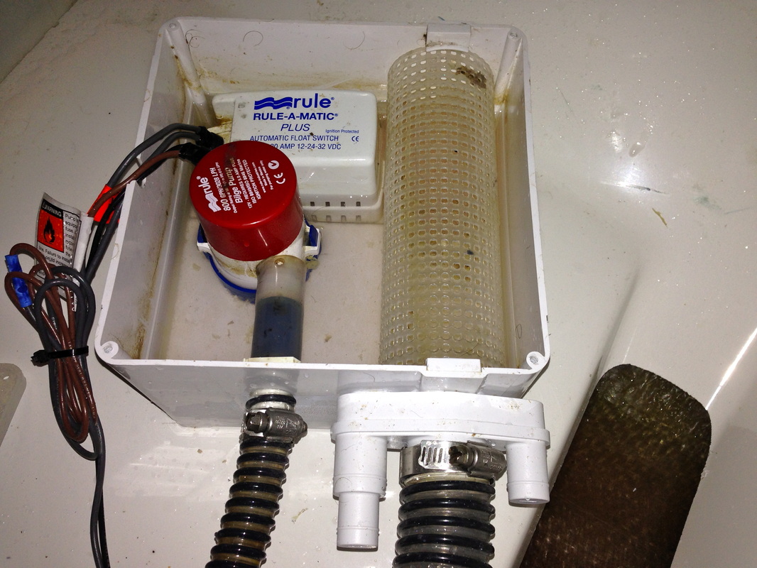
WHEN THE SHOWER SUMP RUNS AND RUNS: This is caused by a stuck float switch. The sump pump is a unit that includes a strainer, a separate float switch and the pump. All contained in a plastic box with a removable lid that is located under the master berth and through a removable floor panel. Power is turned off by turning off the house battery switch. After removing the four screws that secure the lid, all the pieces are easy to access. There is no need to remove the hose clamp or its hose because the interior hose to the pump flexes. The pump is held in by two tangs, squeeze them to the middle of the pump and the pump will be released. The float switch is secured with two screws. Loosen, but do not remove, the one near the wall because the switch base is slid under it. Remove the screw under the stainer and out comes the float switch. Clean this unit annually or as needed.
You know the shower sump box needs cleaning when you open the access panel and you will smell the odor, not like a sewer but like a sink P-trap. The cylinder shaped filter may look clean from the top, just rotate it and you will see the gunk that has collected inside. Gently bend the plastic and out comes the filter. Clean everything well and the smell is gone. Also, there is a small hole in the pump outlet and connecting hose. Do not plug this hole. If it is plugged with the box lid on, the pump will run but will not pump water.
FRESH WATER PUMP OCCASIONALLY CYCLES: The pump does this when there is a small, dripping leak in the system. The question is where is it? Leaks typically happen at a hose clamp and the tug as a forest of them but they are fairly accessible. My experience is the leak is around the water heater so check those first and then check the hose clamps under the galley sink. The two other areas of connections that use hose clamps, besides under the faucets are on through the starboard side cockpit wing lid and forward and through the mid-cabin berth, forward to an inspection panel and this whole wall can be removed.
BILGE PUMP WILL NOT AUTOMATICALLY PUMP: The float switch is a rectangular shaped device on the side of the pump. Don't do what we did and assume the switch is dead. Check the fuse first which is located next to the house battery switch under the port side cockpit storage on the wall and next to the inverter. It is a 5 amp fuse. After finding it, use a label maker and make an easy to find label. This float switch can be tested by removing it from the slot mount and depressing the two circles. If this switch is covered with oil, clean it the outside and this may solve the problem.
BILGE PUMP RUNS AND RUNS: The cause is the automatic float switch. Most often, the surface of the switch needs to be wiped off and remove the sludge, oil, or grime that is causing the circuit to close. Sometimes, the switch is worn out and needs to replaced. You should carry a spare. On Andiamo, the third cause was the switch was right under the drip seal of the packing glan and when that glen was out of adjustment and nearly a small stream of water was constantly striking the float switch, the bilge pump constantly. Once the glan was adjusted to 5 to 10 drops a minute at idle, the problem went away.
CABIN DOOR HANDLE IS LOOSE OR COMES APART: What happened? Inside the mechanism is a threaded nut that is round. There is one for inside handle assembly and the outside handle assembly. In this case, the nut became loose and eventually came off inside the door. The fix: remove the hardware assembly from the inside by removing the rosette bolts. The metric-sized set screws may have to come off also. The two handle assemblies will come off. Put the nut back on and re-assemble.
CABIN DOOR LATCH DOES NOT FULLY SEAT IN THE FRAME: The symptom was the cabin door would open when the tug was rolling from side to side. An assessment showed the striker plate in the frame was mounted 1/16" out of alignment with the door latch. The fix: using a small file and filing down the edge of the striker plate a touch allowed the latch to fully extend into the striker plate.
LOSS OF SPEED AND EFFICIENCY-SMALL BUT NOTICEABLE: The signs and symptoms are a two mile per hour (or knot) loss of speed at the usual RPM's and the percentage of load on the engine at the usual RPM's is about 8-10% higher. This was caused by barnacles on the rudder, propeller and especially the trim tabs. The fix: Getting in the water with the appropriate exposure suit, gloves, and a 2 inch steel paint scraper. Found no need for mask or snorkel because your head is aways above the water. Do the trim tabs first, then the rudder as these are reachable at arms length. Then, hugging the rudder and being under the swim step with head above water, do the prop blades which can be rotated into reach. Whole job takes about an hour.
HOLDING TANK OVERFLOWS: (Also known as "The Hudson River Shit Show." See the description in that section of the Great Loop trip.) There is no minimizing this; it is a smelly and disgusting event that has to be dealt with. The signs & symptoms are the holding tank sensors do not indicate the tank is half full or full, there is a slight and constant odor of sewage in the cabin, there is small trickle fluid coming out of the vent fitting, and the vac-u-flush head sounds different, like it is straining under a load. Also, when flushed, no air or odor is detected from the vent. This vent is located on the starboard side of the hull opposite the sink. When the deck fitting was loosened for a pump-out, fluid sprayed out.
The primary cause is the failure of the holding tank sensors to warn that the tank is full AND the failure to not pump out the tank after 5 days of use by two people. The sensors are outside of the holding tank, glued and uses an electrical current to sense the tank level. These often fail because solids are stuck to the tank's walls thus the electrical circuit is never closed. When this happens, the secondary cause is the contents of the tank will go up the air vent line and the solids will be stopped by the vent fitting's wire strainer. When the tank cannot be vented, it also cannot be fully pumped out.
The fix: pump-out as much as possible and until the vent line can be cleared, release the pressure inside the tank by removing the deck fitting. Remove the vent line from the hull fitting and accessing this is only done by going inside the bowels of the tug. Do this by first removing the refrigerator (it is easy: empty the refrigerator, remove the door, the four plastic covers in each corner that hide the mounting screws, remove the four screws and pull out the refrigerator). Then, crawl into this small space, undo the hose clamp on the back of the vent fitting by laying flat on your back and reaching high up to the hose clamp, remove the hose and put it in a bucket and use a water hose on low pressure against the vent hose to push back the clog. Then, clean out the vent fitting and its wire mesh straining by using air to push back any clog there. Re-assemble and make certain the vent hose is at a constant downward angle from the hull fitting to the holding tank. The pump-out hose and the vent line connections to the holding tank are accessed by going through the mid-cabin, removing the wall that is forward & toward the bow (its easy).
Test the Fix by flushing the toilet. A slight puff air will be felt coming out the hose. Re-assemble the hose line, clean up with a weak bleach/water solution, back out and put the refrigerator back.
Clean the Tank by adding dishwasher detergent to a half tank of water, go cruising for at least hour to splash and agitate the water around and then pump-out. Adding water softener and crush ice to the tank can increase the effectiveness. The ice will act as little scrubbers.
WATER TANK DOES NOT FILL (OR "WE NEED WATER ALREADY?") The cause of this is an inadequate vent to the tank. The vent fitting is on the starboard side of the tug behind the stove. The cause of the blockage is often a bit of water that is at the bottom of a loop in the vent line. The temporary fix is to blow air through the vent fitting when the water level is less than half full. You will confirm that this is the issue when you meet resistance and as you blow, the resistance goes away and there is a slight sucking sound of air. The permanent fix is to examine the vent line and take the dip or sag out of it.
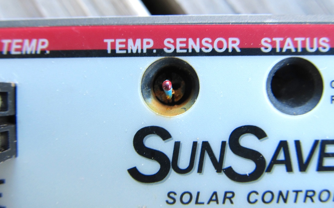
SOLAR PANEL CONTROLLER FAILS: A blinking red light on the Morningstar Remote Meter got my attention. A check of the controller that is located inside the port cockpit storage area showed its LED indicator was flashing red. The owner's manual showed how to do a diagnostic test and to interrupt the error code. Then the LED light was a steady red, meaning that a critical error had occurred. The problem was the failure of the temperature sensor and this photos shows the issue. Morningstar was emailed and they immediately sent a replacement unit. The install was fast and easy. The fix is to keep water off of the unit and a plastic housing was fabricated and installed.
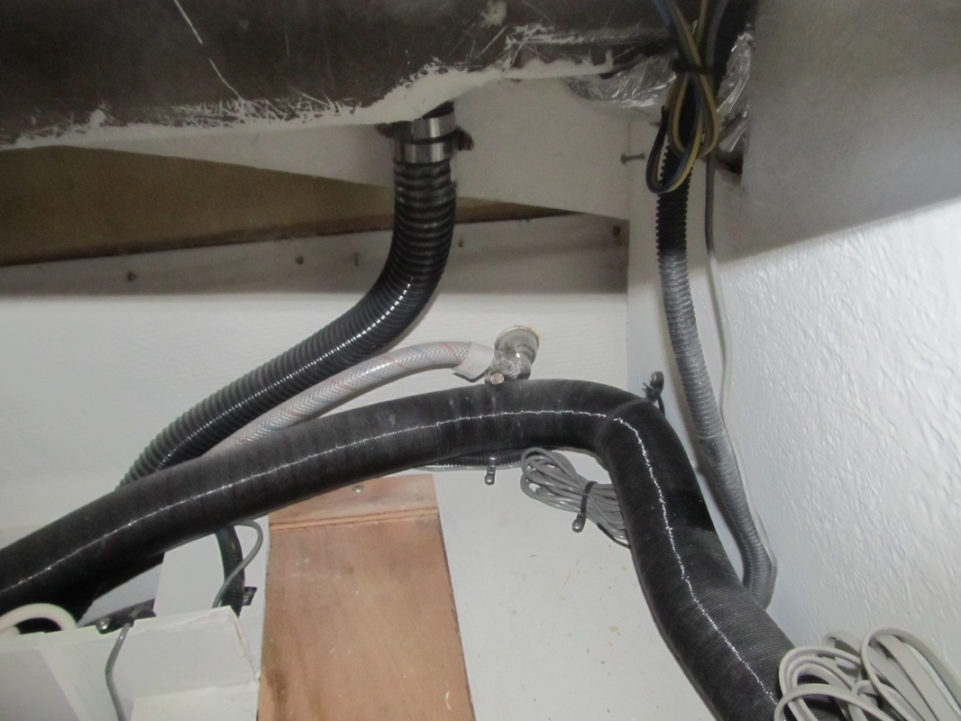
WHAT IS BEHIND THE STOVE? This photo shows the answer after removing the two screws on each side of the stove and the three screws below the oven door. The large flexible tubing that goes across the photo is the duct from the diesel cabin heater. The water fill line is the black one that is in the middle and doing going to the bottom of the photo and next to it is the water tank vent line.
WHAT IS THAT BEEPING SOUND FROM A STATEROOM? Probably it is the CO detector. These are hardwired into the 12 volt system and are active all the time and yes, they are a tiny draw on the battery. If a engine is not running or you are not close to another boat's engine, the issue may the detector itself. The outside shell comes off by squeezing th tabs on each side, at the base and in the middle of the house. This just lifts away. If the red light is on or it is beeping, pull the power wire out of the socket. This is a unit that fits into a socket and disengages easily. Then, blow off any dust, let it sit for a minute or two as it re-boots. The detector may have expired - there is an expiration date on the top of the housing. If the unit needs to replaced, just order one online (about $80) and replace the circuit board, the guts of the detect, leaving the power wire and base plate and you are done. Now, the manufacturer has a new design, so remove the old unit, cut the wires and butt-connect them to the wiring of the new unit.
